
|
|
Frame serial number (Except for Oceania)Стр 1 из 11Следующая ⇒ INTRODUCTION Congratulations on your purchase of the Yamaha DT200FUW). This model is the result of Yamaha's vast experience in the production of fine sporting, touring, and pacesetting racing machines. It represents the high degree of craftsmanship and reliability that have made Yamaha a leader in these fields. This manual will give you an understanding of the operation, inspection, and basic maintenance of this motorcycle. If you have any questions about the operation or maintenance of your motorcycle, please consult a Yamaha dealer. U001 NOTE: ______________________________ Some data in this manual may become outdated due to future improvement on this model. If you have any questions about this manual or your motorcycle, please consult a Yamaha dealer.
SERVICE DIVISION MOTORCYCLE GROUP YAMAHA MOTOR CO., LTD. U-759
ATHINK OF YOUR SAFETY:
They must be correctly maintained at all times in order to ensure optimum performance. However, as a rider you must also ensure that your physical condition is good, and that you are not tired, in order that you too can optimize your vehicle control. Medicines, drugs and alcohol should not be combined with riding, especially alcohol which increases the individual's likelihood of taking risks. Alcohol is dangerous, even in small quantities. Correct protective riding gear is just as much a part of motorcycling safety as the safety belt is in the car; a good leather suit and gloves, sturdy boots and a good quality, properly fitting crash helmet are ideal. But beware: good protective clothing can result in the individual being lulled into a false sense of security. When this happens more risks are taken and speeds increase... this particuiarily applies in wet weather. The good motorcyclist therefore rides defensively and protectively in order to minimize risks. A-305 CONTENTS DESCRIPTION.......................................... 1-1 MOTORCYCLE IDENTIFICATION..... 2-1 Vehicle identification number (For Oceania)...................................... 2-1 Frame serial number (Except for Oceania)........................... 2-1 Engine serial number.......................... 2-2 CONTROL FUNCTIONS........................ 3-1 Main switch.......................................... 3-1 Indicator lights.................................... 3-2 Oil warning light checking method...3-3 "Coolant temp"warning indicator light checking method (For Oceania).......... 3-5 Speedometer....................................... 3-6 Tachometer (Except for Oceania)...... 3-6 Engine temperature gauge (Except for Oceania)................................................ 3-7 Handlebar switches............................. 3-7 Clutch lever.......................................... 3-8 Change pedal....................................... 3-9 Front brake fever..:.............................. 3-9 Rear brake pedal................................. 3-9 Fuel tank cap....................................... 3-9 Fuel cock............................................ 3-10 Starter lever (CHOKE)...................... 3-11 Kick starter......................................... 3-12 Steering lock...................................... 3-12 Helmet holder..................................... 3-14 Side cover removal............................ 3-14 Front forks.......................................... 3-15 Rear shock absorber......................... 3-15 Rear carrier (Except for Oceania)....3-16 Note on handling of the Yamaha Energy Induction System (Y.E.I.S.)..3-16 Y.P.V.S, (Yamaha Power Valve System)........................................... 3-17 Sidestand........................................... 3-18 Sidestand switch operation check...3-18 PRE-OPERATION CHECKS...................... 4-1 Brakes................................................... 4-3 Brake fluid leakage.............................. 4-3 Clutch................................................... 4-4 Throttle grip.......................................... 4-4 Engine oil.............................................. 4-4 Transmission oil.................................. 4-5 Coolant............................................ 4-5 Chain..................................................... 4-5 Tires..................................................... 4-5 Wheels........................................... 4-9 Fittings/Fasteners................................. 4-9 Lights and signals............................... 4-10 Switches.......................................... 4-10 Battery.............................................. 4-10 Fuel..................................................... 4-10 OPERATION AND IMPORTANT RIDING POINTS................................................... 5-1 Starting a cold engine....................... 5-1 Engine warm-up................................... 5-3 Starting a warm engine..................... 5-3 Shifting................................................. 5-4 Engine break-in.................................. 5-4 Parking............................................ 5-5 PERIODIC MAINTENANCE AND MINOR REPAIR................................................... 6-1 Tool kit.................................................. 6-1 Periodic maintenance/lubrication........ 6-3 Torque specifications........................... 6-6 Transmission oil level check................ 6-7 Transmission oil replacement.............. 6-8 Cooling system................................ 6-9 Air filter............................................... 6-14 Carburetor adjustment....................... 6-17 Idle speed adjustment........................ 6-17 Throttle cable adjustment............... 6-18 Spark plug inspection......................... 6-19 Front brake adjustment...................... 6-21 Rear brake adjustment...................... 6-22 Brake light switch adjustment............ 6-22 Checking the front and rear brake pads................................ 6-23 Inspecting the brake fluid level.......... 6-24 Brake fluid replacement..................... 6-25 Clutch adjustment.............................. 6-26 Free play adjustment........................ 6-26 Drive chain slack check.................... 6-27 Drive chain slack adjustment............ 6-28 Drive chain lubrication....................... 6-29 Cable inspection and lubrication........ 6-30 Throttle cable and grip lubrication...6-30 Autolube pump adjustment................ 6-30 Brake and change pedals.................. 6-30 Brake and clutch tevers..................... 6-31 Sidestand............................................ 6-31 Rear suspension................................ 6-31 Front fork inspection.......................... 6-31 Front fork and rear shock absorber adjustment.......................................... 6-32 Rear shock......................................... 6-34 Rear shock absorber adjustment....6-35 Recommended combinations of the front fork and the rear shock absorber settings............................................... 6-37 Steering inspection............................. 6-38 Wheel bearings................................... 6-38 Battery................................................ 6-38 Replenishing the battery fluid............. 6-40 Fuse replacement............................. 6-41 Replacing the headlight bulb.............. 6-42 Headlight beam adjustment............... 6-44 Front wheel removal.......................... 6-44 Front wheel installation...................... 6-45 Rear wheel removal.......................... 6-47 Rear wheel installation....................... 6-48 Troubleshooting.................................. 6-48 Troubleshooting chart......................... 6-49 CLEANING AND STORAGE.................. 7-1 A. Cleaning............................................ 7-1 B. Storage.......................................... 7-2 SPECIFICATIONS.............................. 8-1 WIRING DIAGRAM A-500
1 Tail/Brake tight" 11 2 Rear flasher light 12 3 Side cover 13 4 Air scoop 14 5 Front flasher light 15 6 Radiator 16 7 Kick starter 17. 8 Brake pedal 18 9 Headlight 19 U-002 NOTE: _________ The motorcycle you have purchased may differ slightly from those shown in the photographs. i-i A600 MOTORCYCLE IDENTIFICATION A-602 Engine serial number The engine serial number is stamped into the left side of the engine.
1 Engine serial number U-003 NOTE: _____________________________ The first three digits of these numbers are for model identification; the remaining digits are the unit production number. Keep a record of these numbers for reference when ordering parts from a Yamaha dealer. 2-2
CONTROL FUNCTIONS B-001 Main switch The main switch controls the ignition and lighting systems. Its operation is described below.
LOCK B005 ON: Electrical circuits are switched on. The engine can be started. The key cannot be removed in this position. B-006 OFF: Ail electrical circuits are switched off. The key can be removed in this position. B-007 LOCK: The steering is locked in this position, and all electrical circuits are switched off. The key can be removed in this position. Refer to "Steering lock" (page 3-12) for proper operation. B-012 PARKING {Except for Oceania): The steering is locked in this position, and the tailiight and auxiliary light come on but all other circuits are off. The key can be removed in this position. U-007 NOTE: ______________________________ Always turn the main switch to "OFF" or "LOCK" and remove the key when the motorcycle is unattended. 3-1 B-100 Indicator lights
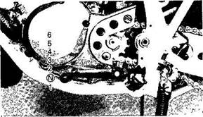
1 "TURN" indicator light 2 "HIGH BEAM" indicator light 3 "NEUTRAL" indicator 4 "OIL" warning indicator light 5 "Coolant temp " warning indicator light B-101 "TURN" indicator light (orange): This indicator flashes when the turn switch is "ON". B-102 "NEUTRAL" indicator light (green): This indicator comes on when the transmission is in neutral. B-103 "HIGH BEAM" indicator light (blue): This indicator comes on when the headlight high beam is used. S-107 "OIL" warning indicator light (red): This indicator comes on when the oil level is low. This light circuit can be checked by the following procedure. U-3O0 3-4 "Coolant temp." warning indicator light checking method (For Oceania)
Warning indicator I light comes on Wait a few seconds.
Warning indicator light goes off.
Electrical circuit is OK. Go ahead with riding.
NOTE: _____________________________ If the main switch is turned off after the warning light goes out and then immediately again the main switch is turned on, the warning light may not come on. This is not because of failure. B-400 Speedometer
The odometer and trip odometer are built into the speedometer. The trip odometer can be reset to "0" with the reset switch. Use the odometer to estimate how far you can ride on a tank of fuel before going to "RESERVE". This information will enable you to plan fuel stops in the future. B403 Clutch lever The clutch lever is located on the left handlebar; it disengages or engages the clutch. Pull the clutch lever to the handlebar to disengage the clutch, and release the lever to engage the clutch. The lever should be pulled rapidly and released slowly for smooth starts. 3-8 B-aoo Change pedal
The gear ratios of the constant-mesh 6-speed transmission are ideally spaced. The gears can be shifted by using the change pedal on the left side of the engine. B-900 Front brake lever The front brake lever is iocated on the right handlebar. Pull it toward the handlebar to activate the front brake. B-901 Rear brake pedal The rear brake pedal is on the right side of the motorcycle. Press down on the brake pedal to activate the rear brake. C-003 Fuel tank cap 1. To remove the tank cap, insert the key in the lock and turn the key 1 /4 turn counterclockwise. Rotate the cap 1/4 turn counterclockwise and remove it from the tank. 3-9
1 Fuel tank cap U-013 NOTE: 2 Open 2. To reinstall the tank cap, set the cap in the filler neck and rotate the cap 1 /4 turn clockwise. Lock the cap by turning the key 1/4 turn clockwise, and remove the key. U-611 .WARNING: Fuel cock The fuel cock supplies fuel from the tank to the carburetor while filtering the fuel. The fuel cock has three positions: 3-10
OFF: With the lever in this position, fuel will not flow. Always return the lever to this position when the engine is not running. ON: With the lever in this position, fuel flows to the carburetor. Normal riding is done with the lever in this position. RES: This indicates reserve. If you run out of fuel while riding, move the lever to this position. FILL THE TANK AT THE FIRST OPPORTUNITY BE SURE TO SET THE LEVER TO "ON" AFTER REFUELLING. 3-11 C-205 Starter lever (CHOKE)
When cold, the engine requires a richer air-fuel mixture for starting. A separate starter circuit supplies this mixture. Pull the starter lever up to open the circuit for starting. When the engine has warmed up, push the lever down to close the circuit. C602 Kick starter
Rotate the kick starter away from the engine. Push the starter down lightly with your foot until the gears engage, then kick smoothly and forcefully to start the engine. This model has a primary-coupled kick starter so the engine can be started in any gear if the clutch is disengaged. In normal practice, however, shift to neutral before starting. C-301 Steering lock 1. Combined with main switch The steering is locked when the main switch is turned to "LOCK." To lock the steering, turn the handlebars all the way to the left or right. With the key at "OFF," push it into the main switch, turn it counterclockwise to "LOCK," and remove it. To release the lock, turn the key clockwise.
3-12
1 Push 2 Release 3 Turn 2. Separate (Except for Oceania) To lock the steering, turn the handlebars all the way to the right, and insert the key into the steering lock. Turn the key 1 /8 turn counterclockwise, push it in, then turn it 1 /8 turn clockwise. After checking to see that the lock is engaged, remove the key from the lock. To release the lock, reverse the above procedure.
U-614 ZM/VA RIMING: Never turn the key to "LOCK" when the motorcycle is moving. 3-13 C-500 Helmet holder To open the helmet holder, insert the key in the lock and turn it as shown. To lock the helmet holder, replace the holder in its original position. U-615 ^WARNING: Side cover removal
Remove the screw. Then remove the side cover by pulling out the knob. 3-14
C-800 Front forks The front forks of this model are pneu-momechanical; namely, there is a combination air and mechanical coil spring in the inner tubes. By adjusting the air pressure, you can alter the suspension to suit the motorcycle's load and the operating conditions. Refer to page 6-32 for proper adjustment procedures. C-900 Rear shock absorber The spring preload and the damping of the rear shock absorber can be adjusted to suit the motorcycle's load (ex: optional accessories etc.) and riding conditions. Refer to page 6-35 for proper adjustment procedures. 3-15
1 Spring preload adjuster 2 Damping adjuster D550 Sidestand This model is equipped with an ignition circuit cut-off system. The motorcycle must not be ridden when the sidestand is down. The side-stand is located on the left side of the frame. (Refer to page 5-2 for an explanation of this system.)
\WARNING: This motorcycle must not be operated with the sidestand in the down position. If the stand is not properly retracted, it could contact the ground and distract the operator, resulting in a possible loss of control. Yamaha has designed into this motorcycle a lockout system to assist the operator in fulfilling the responsibility of retracting the sidestand. Please check carefully the operating instructions listed below and if there is any indication of a malfunction, you must return the motorcycle to a Yamaha dealer immediately for repair.
PRE-OPERATION CHECK Before using this motorcycle, check the following points:
4-1 NOTE; _____________________________________________________________________ Pre-operation checks should be made each time the motorcycle is used. Such an inspection can be thoroughly accomplished in a very short time; and the added safety it assures is more than worth the time involved. ^WARNING: Brake fluid leakage Apply each brake for a few minutes. Check to see if any brake fluid leaks out from the pipe joints or the master cylinder(s). 4-3
U-625 \W A RIM ING: If brake fluid leakage is found, ask a Yamaha deafer for immediate repairs. Such leakage could indicate a hazardous condition.
Engine oil
Make sure the engine oil is at the specified level. Add oil as necessary.
4-4 Transmission oil {See page 6-7 for details) Make sure the transmission oil is at the specified level. Add oil as necessary.
E600 Coolant Check the coolant level in the reservoir tank when the engine is cold. {The coolant level will vary with engine temperature.} The coolant level is satisfactory if it is between the FULL and LOW marks on the tank. If the coolant level is at or below the LOW level, add tap water (soft water) to bring the level up to FULL. Change the coolant every two years. (See page 6-9 for details.) 4-5 U-626 AWARMIMG:
U-309 Tires To ensure maximum performance, long service, and safe operation, note the following: 1. Tire air pressure Always check and adjust the tire pressure before operating the motorcycle. U-675 AWARNING: Tire inflation pressure should be checked and adjusted when the temperature of the tire equals the ambient air temperature. Tire inflation pressure must be adjusted according to total weight of cargo, rider, passenger, and accessories (fairing, saddlebags, etc. if approved for this model), and vehicle speed.
U-677 A WARN ING: Proper loading of your motorcycle is important for the handling, braking, and other performance and safety characteristics of your motorcycle. Do not carry loosely packed items that can shift. Securely pack your heaviest items close to the center of the motorcycle, and distribute the weight evenly from side to side. Properly adjust the suspension for your load, and check the condition and pressure of your tires. NEVER OVERLOAD YOUR MOTORCYCLE. Make sure the total weight of the cargo, rider, passenger, and accessories {fairing, saddlebags, etc. if approved for this model) does not exceed the maximum load of the motorcycle. Operation of an overloaded motorcycle could cause tire damage, an accident, or even injury.
*Load is the total weight of cargo, rider, and accessories 2. Tire inspection Always check the tires before operating the motorcycle. If center tread depth reaches the limit as shown, if the tire has a nail or glass fragments in it, or if the side wall is cracked, contact a Yamaha dealer immediately and have the tire replaced.
1 Tread depth 2. Side wall FRONT:
REAR
AWARNING: After extensive tests, the tires mentioned below have been approved by Yamaha Motor Co., Ltd. for this model. No guarantee for handling characteristics can be given if tire combinations other than what is approved are used on this motorcycle. The front and rear tires should be of the same manufacture and design. EUU12600 MOTE: _____________________________ These limits may be different by regulation from country to country. If so, conform to the limits specified by the regulations of your own country.
U-700 AWARNING: 1. Operating the motorcycle with exces 2. Patching a punctured tube is not
Wheels To ensure maximum performance, long service, and safe operation, note the following: 1. Always inspect the wheels before a ride. Check for cracks, bends, or warpage of the wheel; be sure the spokes are tight and undamaged. If any abnormal condition exists in a wheel, consult a Yamaha dealer. Do not attempt even small repairs to the wheel. If a wheel is deformed or cracked, it must be replaced. 2. Tires and wheels should be balanced 3. After installing a tire, ride conservatively E8S0 Fittings/Fasteners Always check the tightness of chassis fittings and fasteners before a ride. Use the chart on page 6-6 to find the correct torque. 4-9
E-700 Lights and signals Check the headlight, flasher lights, taillight, brake light, meter lights, and all the indicator fights to make sure they are in working condition. E-704 Switches Check the operation of the headlight switch, turn switch, brake light switch, horn switch, main switch, etc. E-705 Fuel Make sure there is sufficient fuel in the tank. U-610 .WARNING:
Do not overfill the fuel tank. Avoid spilling fuel on the hot engine. Do not fill the fuel tank above the bottom of the filler tube as shown in the illustration or it may overflow when the fuel heats up later and expands. 4-10 E809
For Australia: Unleded fuel only Fuel tank capacity: Total: 10 L (2.2 Imp gal, 2.6 US gal) Reserve: 1.8 L (0.4 Imp gal, 0.5 US gal) 4-11 F-000 5-1 U-709 AWARNING: Before going through the following steps, check the function of the sidestand switch. (Refer to page 3-19.)
IF TRANSMISSION IS IN NEUTRAL AND SIDESTAND IS DOWN IF TRANSMISSION IS IN GEAR AND SIDESTAND IS UP
RETRACT SIDESTAND AND PUT TRANSMISSION IN GEAR
MOTORCYCLE CAN BE RIDDEN PULL IN CLUTCH LEVER AND KICK THE KICK STARTER, ENGINE WILL START
1. Turn the fuel cock to "ON." 2. Turn the ignition key to "ON" and the en 3. Shift transmission into neutral. U-030 NOTE: _____________________________ When the transmission is in neutral, the neutral indicator tight (green) should be on. If the light does not come on, ask a Yamaha dealer to inspect it. F-110 Engine warm-up To ensure maximum engine life, always warm up the engine before riding your motorcycle. Never accelerate hard with a cold engine. An engine is warm if it responds normally to the throttle when the starter (CHOKE) is turned off. F-108 Starting a warm engine The starter (CHOKE) is not required when the engine is warm.
4. 5. Kick the kick starter to start the engine. 6. After the engine starts, warm it up for one U-314 See "Break-in section" prior to operating the motorcycle for the first time. 5-3 F-200 Shifting The transmission lets you control the amount of power you have available at a given speed for starting, accelerating, climbing hills, etc. The use of the change pedal is shown in the illustration. (Page 3-9} To shift into NEUTRAL, depress the change pedal repeatedly until it reaches the end of its travel (you will feel a stop when you are in first gear), then raise the pedal slightly. U-315 1. Do not coast for long periods with the engine off, and do not tow the motorcycle a long distance. Even with gears in neutral, the transmission is only properly lubricated when the engine is running. Inadequate lubrication may damage the transmission. 2. Always use the clutch when changing gears. The engine, transmission, and driveline are not designed to withstand the shock of forced shifting and can be damaged by shifting without the clutch.
Engine break-in There is never a more important period in the life of your motorcycle than the period between zero and 1,000 km (600 mi). For this reason we ask that you carefully read the following material. Because the engine is brand new, you must not put an excessive load on it for the first 1,000 km (600 mi). The various parts in the engine wear and polish themselves to the correct operating clearances. During this period, prolonged full throttle operation, or any condition which might result in excessive heating of the engine, must be avoided. 5-4 F-309 1. 2. U354 0-500 km (0-300 mi): Avoid operation above 6.000 r/min. Stop the engine and let it cool for 5 to 10 minutes after every hour of operation. Vary the speed of the motorcycle from time to time. Do not operate it at one set throttle position. 500-1,000 km (300-600 mi): Avoid prolonged operation above 7.000 r/min. Rev the motorcycle freely through the gears, but do not use full throttle at any time.
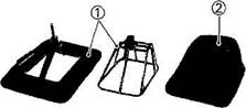
1,000 km (600 mi) and beyond: Full throttle can be used. U387 Parking When parking the motorcycle, stop the engine and remove the ignition key. Turn the fuel cock to "OFF" whenever stopping the engine. 5-5 U-630 WARNING: The muffler and exhaust pipe are hot. Park the motorcycle in a place where pedestrians or children are not likely to touch the motorcycle. Do not park the motorcycle on a slope or soft ground; the motorcycle may overturn. 5-6 PERIODIC Tool kit The service information included in this manual is intended to provide you, the owner, with the necessary information for completing some of your own preventive maintenance and minor repairs. The tools provided in the owner's tool kit are sufficient for most of these purposes; however, a torque wrench is also necessary to properly tighten nuts and bolts. 6-1 U-671
^WARNING: Modifications to this motorcycle not approved by Yamaha may cause loss of performance, and render it unsafe for use. Consult a Yamaha dealer before attempting any changes. 1 Tool kit u 060 NOTE: _____________________________ If you do not have a torque wrench available during a service operation requiring one, take your motorcycle to a Yamaha dealer to check the torque settings and adjust them as necessary. 6-2
6-3 Unit km (miles}
It is recommended that these items be serviced by a Yamaha dealer Medium weight wheel bearing grease Lithium soap base grease 6-4 NOTE: _____________________________________________________________________ Brake fluid replacement: 1. When disassembling the master cylinder or caliper cylinder, replace the brake fluid. Normal 2. On the inner parts of the master cylinder and caliper cylinder, replace the oil seals every two 3. Replace the brake hoses every four years, or if cracked or damaged.
H 301 Torque specifications Use a torque wrench to tighten these items. It is recommended that these items be checked occasionally, especially before a long trip. Always check the tightness of these items whenever they are loosened for any reason.
6-6
6-8
5. Add oil through the oil filter hole. 1 Oil filler cap
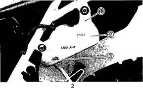
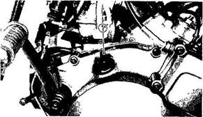
EAHS1300 Cooling system The coolant is circulated by an impeller type pump mounted on the right-hand crankcase and driven by a gear. The coolant is drawn by the pump from the bottom tank of the radiator, through the piped), and discharged into the cylinder and cylinder-head. The coolant passes from the cylinder to the cylinder-head through coolantpassages. After circulating around the combustion chamber jacket, it enters the radiator upper tank via the pipe(2). The heated coolant from the engine then passes down through the finned tubes to the bottom tank of the radiator. These finned tubes present a large surface area to the air and dissipate the heat.
6-9
1. If your motorcycle overheats EUU70500 WVARNING: Do not remove the radiator cap when the engine and radiator are hot. Scalding hot fluid and steam may be blown out under pressure, which could cause serious injury. When opening the radiator cap, note the following points. Wait until the engine has cooled. Place a thick rag like a towel over the radiator cap and slowly rotate the cap counterclockwise to the detent. This procedure allows any residual pressure to escape. When the hissing sound has stopped, press down on the cap while turning counterclockwise and remove it.
6-10
I Engine overheating Check the cooling system for leakage. Wait until the temp gauge indicates lower than 50°C (122°F) line (see page 3-7)
No leakage
OK
NOTE: If it is difficult to get the recommended coolant, tap water can be temporarily used, provided that it is changed to the recommended coolant as soon as possible. 2. Changing the coolant a. Remove the air scoop and side cover. 6-11
1 Stopper bolt c. Place a container under the engine. d. Remove the drain bolt.
1 Dram bolt e. Disconnect the reservoir tank hose on the reservoir tank side, and drain the reservoir tank of its coolant. 6-12
1 Reservoir tank hose 2. "FULL" level 3. "LOW" level f. Drain the coolant completely and g. Retighten the drain bolt. If the gasket is Drain bolt torque: 10 Nm {1.0 nrkg, 7.2 ft-lb)
High quality ethylene glycol antifreeze containing corrosion inhibitors for aluminum engines. Coolant and water mixed ratio: 50%/50% Total amount: 1.200 cm3 (1.06 Imp qt, 1.27 US qt) Reservoir tank capacity: 300 cm3 (0.26 Imp qt, 0.32 US qt) From LOW to FULL level: 240 cm3 (0.21 Imp qt, 0.25 US qt)
Air filter 1. Remove the side cover. 6-14 2. Remove the air filter case fitting screws and the filter case cover.
3. Side out the guide together with the element.
4. Remove the element from its guide, and clean it with solvent. After cleaning, remove the remaining solvent by squeezing the element. 6-15
6. When installing the element in its case, be sure its sealing surface matches the sealing surface of the case so there is no air leak. The element should be cleaned at the specified intervals. It should be cleaned more often if the motorcycle is operated in dusty or wet areas.
1 Guide 2 Element 5. Apply recommended oil to the entire surface of the filter and squeeze out the excess oil. The element should be wet but not dripping. U326 Carburetor adjustment The carburetor is a vital part of the engine and requires very sophisticated adjustment. Most adjustments should be left to a Yamaha dealer who has the professional knowledge and experience to do so. However, the following point may be serviced by the owner as part of this routine maintenance. U-330 H-901 Idle speed adjustment 1. Start the engine and warm it up for a few 2. Set the idle to the specified engine speed
The carburetor was set at the Yamaha factory after many tests. If the settings are disturbed, poor engine performance and damage may result. 6-17 1 Throttle stop screw
 Живите по правилу: МАЛО ЛИ ЧТО НА СВЕТЕ СУЩЕСТВУЕТ? Я неслучайно подчеркиваю, что место в голове ограничено, а информации вокруг много, и что ваше право...  Что делает отдел по эксплуатации и сопровождению ИС? Отвечает за сохранность данных (расписания копирования, копирование и пр.)...  ЧТО ПРОИСХОДИТ ВО ВЗРОСЛОЙ ЖИЗНИ? Если вы все еще «неправильно» связаны с матерью, вы избегаете отделения и независимого взрослого существования...  Система охраняемых территорий в США Изучение особо охраняемых природных территорий(ООПТ) США представляет особый интерес по многим причинам... Не нашли то, что искали? Воспользуйтесь поиском гугл на сайте:
|
 TECHNICAL PUBLICATIONS

 Both motorcycles and mopeds are fascinating vehicles which give a tremendous feeling of freedom to their riders.
 DESCRIPTION
 B-OOO
B-OOO

 Except for Oceania
 PARKING
 Main switch "ON"


 Warning indicator light does not come on.


 Warning indicator light does not go off.


 Ask a Yamaha dealer to inspect electrical circuit.
 3-5
3-5


 D-30S
D-30S E-200
E-200
 Do not remove the radiator cap when the engine is hot.
 1 Reservoir tank 3. "LOW" level
 4-6
4-6 4-7
4-7
 Minimum tire tread depth (front and rear)
 U-678
U-678 E-934
E-934
 Recommended fuel: Regular gasoline
 TURN MAIN SWITCH TO "ON" AND ENGINE STOP SWITCH TO "RUN"


 _L
_L


 T
T ±
±
 Operate the starter (CHOKE) and com
 F300
F300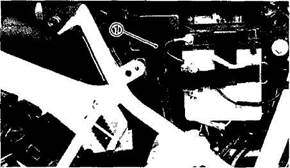
 6-5
6-5
 EAH44S00


 If overheating is detected, perform the following checks.

 Restart the engine If the engine overheats again, ask a Yamaha dealer to inspect and repair it,
 b. Remove the stopper bolt and then remove the radiator cap.
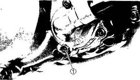


 h. Reinstall the reservoir tank hose, i. Pour the recommended coolant into the radiator until the radiator is full.
 Recommended coolant:
 6-13
6-13


 Standard idle speed: 1,300-1,400 r/min